
Cat Weight Chart
Is your cat a healthy weight? Numbers alone can mislead — a lean Maine Coon can weigh twice as much as an overweight Siamese — so this chart combines typical weight ranges by breed and age with the body condition score vets use. Print the charts, weigh your cat regularly and log it in the tracker to spot changes early.
- Instant download
- Editable Excel & Word
- Print-ready PDF
- 7-day refund
5 files · PDF, XLSX, DOCX
Cat Weight Chart Pack
Printable cat weight charts by breed and kitten age, a body condition score chart, a monthly weight tracker and an Excel weight log with percentage change.
- Breed chart (PDF/XLSX)
- Kitten chart (PDF/XLSX)
- BCS chart (PDF)
- + 2 more
$5.00 USD, one-time 5 files · about $1.00 each
- Instant download
- 7-day refund
- Secure checkout by Stripe
7-day money-back guarantee. Full refund within 7 days of purchase, even after you download.
Free sample: Cat Breed Weight Chart (PDF, 57 KB)

Cat Weight Chart Pack
Printable cat weight charts by breed and kitten age, a body condition score chart, a monthly weight tracker and an Excel weight log with percentage change.
- Breed chart (PDF/XLSX)
- Kitten chart (PDF/XLSX)
- BCS chart (PDF)
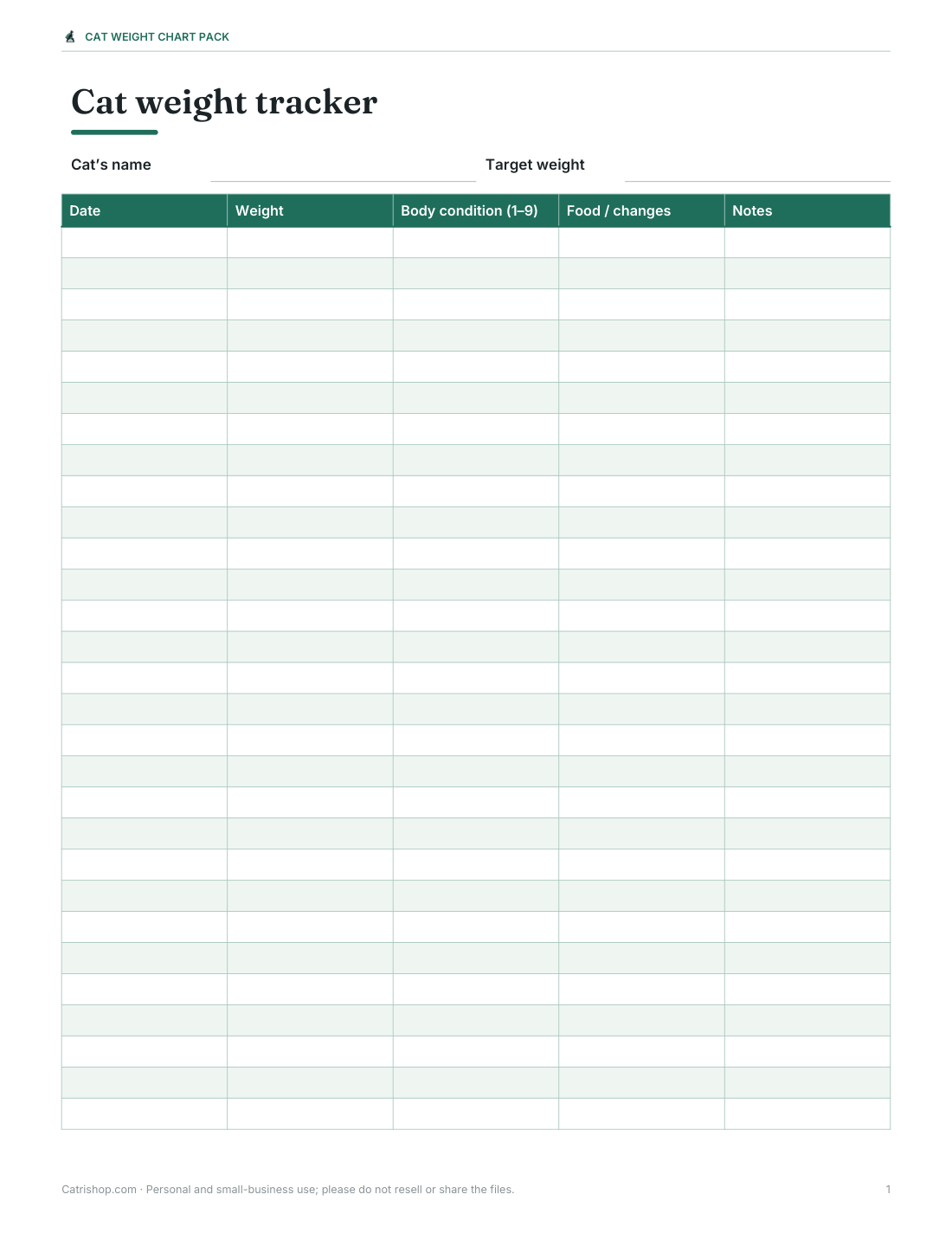
- Monthly tracker (PDF/DOCX)
- Weight log (XLSX)
Formats: PDF, XLSX, DOCX. Instant download after payment (link valid 72 hours, up to 5 downloads). AI-assisted: the templates were drafted with AI help and reviewed and laid out before publishing.
$5.00 USD, one-time 5 files · about $1.00 each
- Instant download
- 7-day refund
- Secure checkout by Stripe
7-day money-back guarantee. Full refund within 7 days of purchase, even after you download.
Free sample: Cat Breed Weight Chart (PDF, 57 KB)
Full refund within 7 days — see the refund policy and license.
Free printables
Single sheets you can print right now, no sign-up. The full pack adds every sheet in one download plus the editable files.
 Printable Cat Breed Weight Chart
 Printable Kitten Weight Chart
 Printable Cat Body Condition Chart
 Printable Cat Weight Chart
 Printable Cat Weight Log
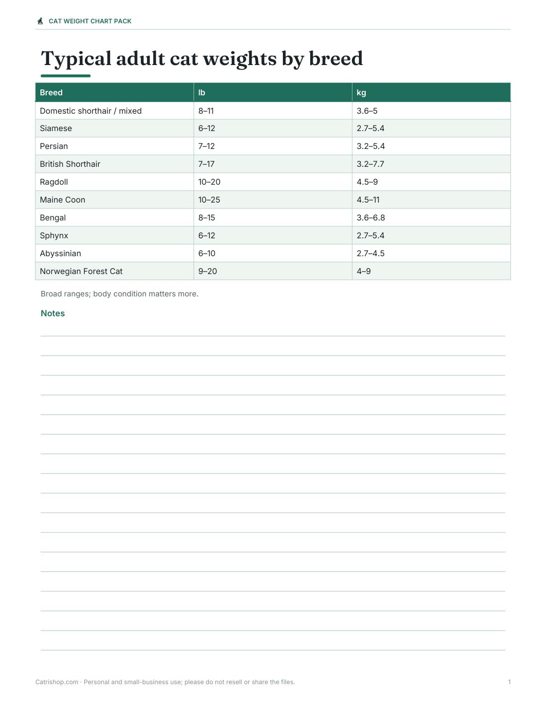
Typical adult weight by breed
| Breed | Typical adult weight | Notes |
|---|---|---|
| Domestic shorthair / mixed | about 8–11 lb (3.6–5 kg) | Wide natural variation |
| Siamese | about 6–12 lb (2.7–5.4 kg) | Slender build |
| Persian | about 7–12 lb (3.2–5.4 kg) | Cobby, stocky body |
| British Shorthair | about 7–17 lb (3.2–7.7 kg) | Males notably heavier |
| Ragdoll | about 10–20 lb (4.5–9 kg) | Large, slow to mature |
| Maine Coon | about 10–25 lb (4.5–11 kg) | Large breed; males much bigger |
| Bengal | about 8–15 lb (3.6–6.8 kg) | Muscular |
| Sphynx | about 6–12 lb (2.7–5.4 kg) | Hairless but sturdy |
| Abyssinian | about 6–10 lb (2.7–4.5 kg) | Lean and athletic |
| Norwegian Forest Cat | about 9–20 lb (4–9 kg) | Large, slow-maturing |
These are broad ranges quoted in breed guides; males are usually heavier than females. A cat can sit within the range and still be over- or underweight for its frame, which is why body condition matters more than the number.
Kitten weight by age
| Age | Typical weight |
|---|---|
| Birth | about 3–4 oz (85–115 g) |
| 1 week | about 4–6 oz (115–170 g) |
| 2 weeks | about 6–8 oz (170–225 g) |
| 4 weeks | about 10–14 oz (285–400 g) |
| 8 weeks | about 2 lb (0.9 kg) |
| 12 weeks | about 3 lb (1.4 kg) |
| 4 months | about 4 lb (1.8 kg) |
| 6 months | about 5–7 lb (2.3–3.2 kg) |
| 12 months | close to adult weight (large breeds keep growing to 3–4 years) |
A common rule of thumb is that kittens gain roughly 1 lb (about 450 g) a month for their first five to six months. Weigh young kittens daily or every few days; a kitten that stops gaining or loses weight should see a vet promptly.
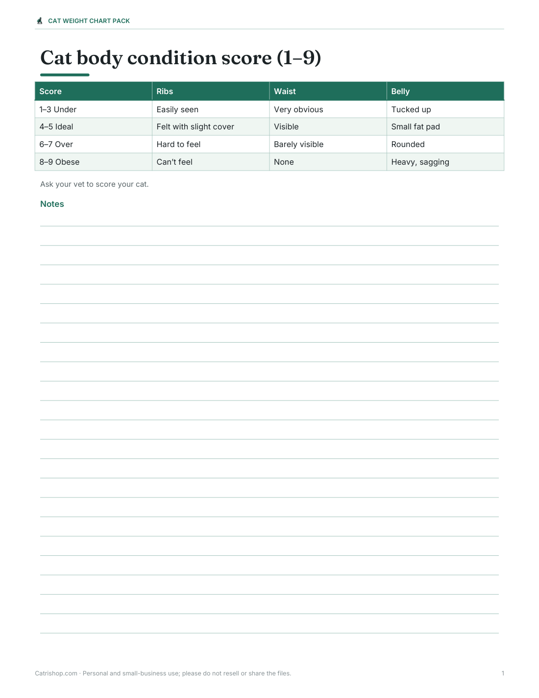
Body condition score (BCS)
| Score (1–9) | Description |
|---|---|
| 1–3: Underweight | Ribs, spine and hip bones easily seen or felt with no fat cover; obvious waist; little muscle |
| 4–5: Ideal | Ribs easily felt with a slight fat covering; waist visible behind the ribs; small belly fat pad |
| 6–7: Overweight | Ribs hard to feel under fat; waist barely visible; rounded belly |
| 8–9: Obese | Ribs can’t be felt; no waist; heavy fat on belly, face and limbs |
Vets often estimate that each point above 5 on the 9-point scale represents roughly 10% extra body weight. Ask your vet to score your cat and suggest a target weight.
How to weigh your cat at home
- Weigh yourself on bathroom scales and note the number.
- Pick up your cat and weigh yourself again.
- Subtract the first number from the second.
- For small kittens or accuracy, use a kitchen or baby scale with a box on it (tare the box).
- Weigh at the same time of day, about monthly for adults and weekly for kittens or cats on a diet.
Worked example
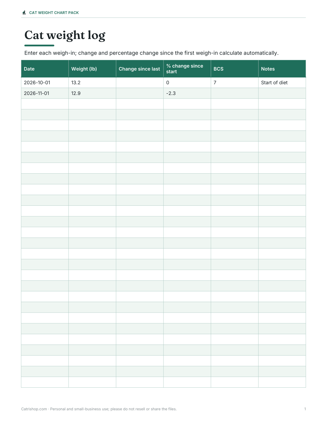
A domestic shorthair weighs 13.2 lb and her vet scores her 7 out of 9. At roughly 10% per point above 5, she is about 20% over her ideal weight, suggesting a target around 11 lb. A safe rate of loss for cats is usually small — often around 0.5–2% of body weight per week — so the vet may plan for her to reach the target over several months. The Excel tracker records each weigh-in and shows the percentage change.
Why weight matters
- Overweight cats are at higher risk of diabetes, arthritis and urinary problems.
- Unexplained weight loss can be a sign of illness such as hyperthyroidism, kidney disease or dental problems.
- Cats should never be put on crash diets — rapid weight loss can cause serious liver disease (hepatic lipidosis).
- Changes of more than a few percent without a reason are worth mentioning to your vet.
Formats and printing
Charts and trackers print on US Letter and A4; the weight log is an Excel workbook that also opens in Google Sheets.
AI-assisted content
Charts were drafted with AI assistance and reviewed before publishing. They are general information, not veterinary advice — your vet can assess your individual cat.
Frequently asked questions
What is a healthy weight for a cat?
Many domestic cats weigh about 8–11 lb, but breed and frame matter; body condition score is the best guide.
How much should a kitten weigh?
Roughly 1 lb per month of age for the first five to six months.
What is a body condition score?
A 1–9 (or 1–5) scale vets use to judge fat cover; 4–5 on the 9-point scale is ideal.
How can I weigh my cat at home?
Weigh yourself holding the cat, then subtract your own weight.
How fast should an overweight cat lose weight?
Slowly — often about 0.5–2% of body weight per week, under a vet’s guidance.
Is this a subscription?
No, it is a one-time download.